In the first post in this series I deployed a Harvester cluster to my home lab servers. Before I get into deploying virtual machines though, I want to make some common configuration updates to my cluster. For instance, I want my virtual machine network traffic to be placed on a different network. Placing the small amount of network traffic that my virtual machines might be using on their own NIC is probably not necessary in my lab. But I wanted to build the lab in a way that somewhat mimics the way virtual machines are deployed in production environments so I can see how it works. When deploying VMware ESXi hosts, I would commonly have several virtual machine networks on their own NIC, each on their own VLAN. In this post we’ll deploy a Harvester virtual machine network.
Network Configs
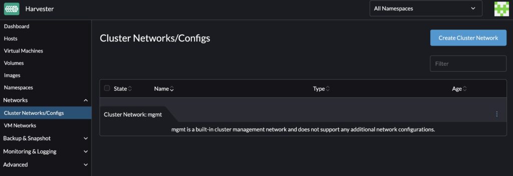
From the Harvester console, click on the Cluster Networks/Config menu. From here click the Create Cluster Network button.
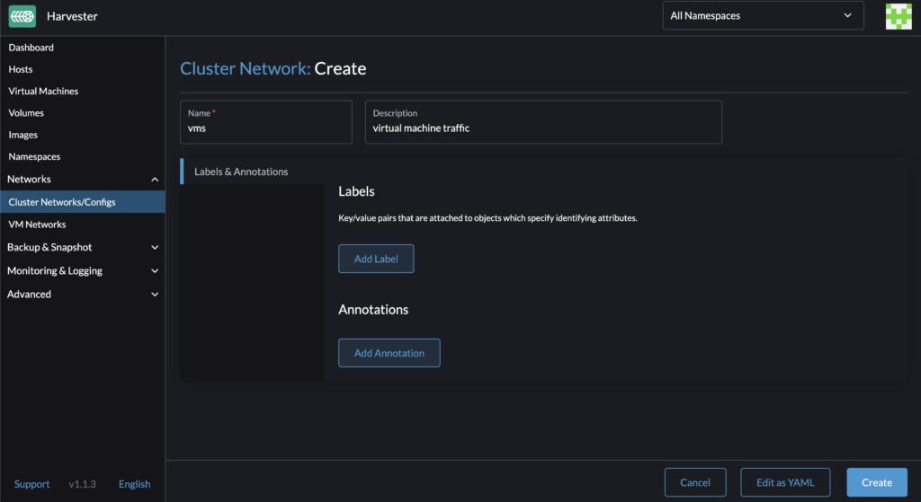
In the Cluster Network page there isn’t too much to do. Give the Cluster Network a name and a description. You an also add some additional metadata in the form of Labels and Annotations. When you’ve completed this task, click Create.
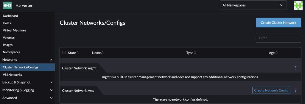
After you click the create button you’ll be taken back to the " Cluster Networks/Configs" page. You’ll see that I’ve got a mgmt network listed. This comes from the management network that was configured when standing up the Harvester nodes in our first post. There is also a new network that we just created a moment ago. Click the Create Network Config button on the new network named “vms.”
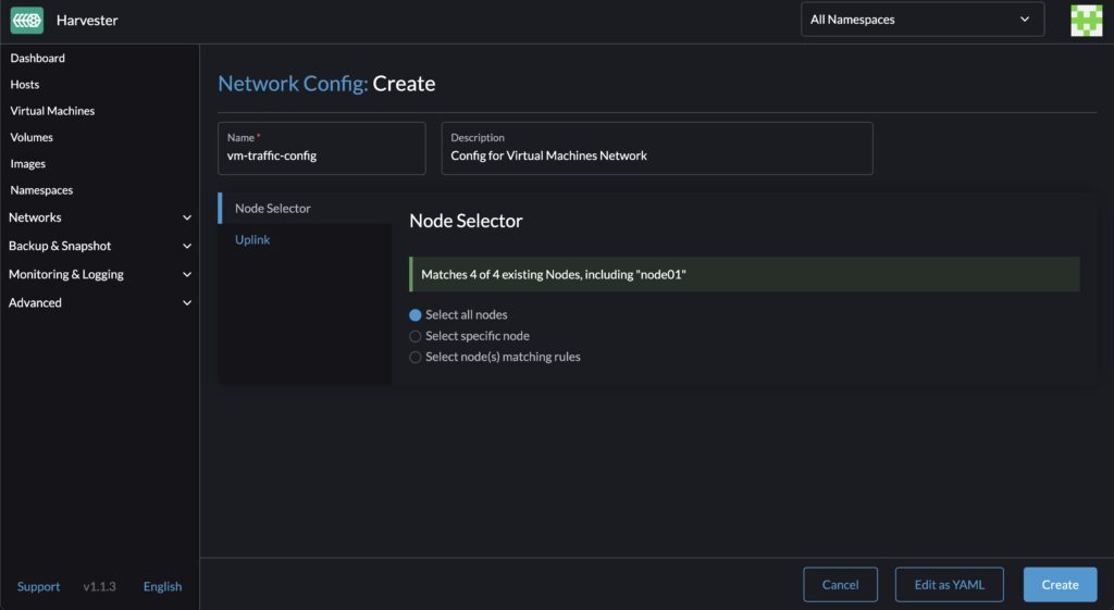
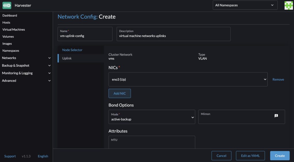
In the network config settings, you’ll need to give the config a name and a description as well. Then you’ll begin the task of assigning the config to the nodes and telling them which NIC to use. In the Node Selector section, you have a few choices to define what Harvester nodes to assign this network config to. In my case I want every node in my cluster to be assigned the same config so I’ll choose " Select all nodes". You can also pick specific nodes or match nodes based on a label selector. Click the Uplinks menu of the config next.
On the uplinks screen, choose the physical NIC to assign this config to. On all of my nodes, I want the interface " eno3" configured. I’m only using one NIC (not so production worthy now is it?) so the bond can be left as active-backup. Then click the Create button.
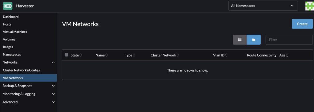
The config is done but now we can create a set of VM Networks. Navigate to the VM Network page and click the Create button.
Here we’ll leave the namespace default and give it a name and description as is becoming a common task. In the Basics tab, I want to set my Type to " L2VlanNetwork" because the physical network I’m connecting to is an 802.11q trunk port, also called a Tagged VLAN in some parlance. I then want to set the VLAN to one of the VLANs I tagged on the physical network, in my case VLAN 150 is my virtual machine VLAN. Then in the last drop down, select the Cluster Network we configured earlier in this post. Then click the Route tab.
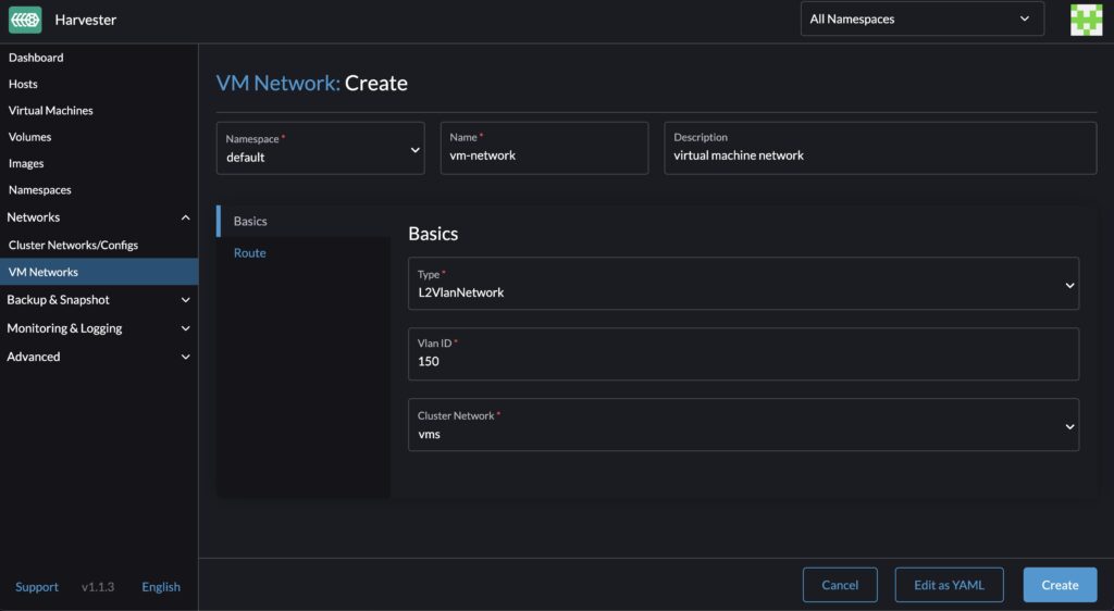
In the Route tab, you can select how your virtual machines will get their IP Addresses assigned. If you choose the DHCP option, then you can specify the IP address of the DHCP server. In my situation, I don’t have a DHCP server setup on my network, so I’ll choose the Manual option and specify the network CIDR and gateway. Then click Create.

When you’ve completed your task, you’ll see the VM Network available in your summary screen.
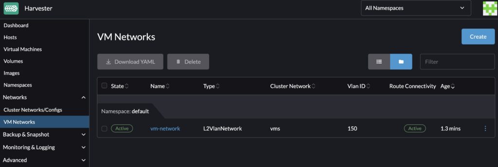
At this point, if you deploy a virtual machine, you can specify this VM Network to define how the virtual machine’s network traffic is passed to the physical network over your specified VLAN across a set of defined physical NICs. This is precisely what we’re going to do in our next post within this series.